|

| Site Partners: | SpotterGuides | Veloce Books |
| Related Sites: | Your Link Here |
|
||||||||||
|
||||||||||
 18 Feb 2007, 09:10 (Ref:1844177)
|
#76 | ||
|
Veteran
Join Date: Aug 2002
Posts: 1,686
 |
The fact that they had to give the 4 stroke GP bikes 490cc's AND a weight advantage tells you how much potential 2 strokes have. Especially when you also realise that the spent their entire time trying to get the bike to cope with the engine, not the other way round.
It's just a shame that GP politics/vested interest and the Bimota V-due disaster (caused by poor quality control) has killed off 2 strokes for the moment. |
||

|

|
|
18 Feb 2007, 19:14 (Ref:1844536)
|
#77 | |||
|
Racer
Join Date: Jan 2007
Posts: 158
|
Quote:
|
|||
|
|
__________________
Error 0xffff - Signature Of The Day program has gone off in a huff!
|
|
18 Feb 2007, 23:18 (Ref:1844953)
|
#78 | ||
|
Veteran

Join Date: Apr 2006
Posts: 1,916
|
Maybe even Morocco or Tunisia
|
||
|
|
__________________
Contrary to popular opinion, I do have mechanical sympathy, I always feel sorry for the cars I drive.
|
|
19 Feb 2007, 10:24 (Ref:1845362)
|
#79 | |
|
Veteran

Join Date: Apr 2002
Posts: 9,710
|
or that 3rd world country of Europe . . .the one with the cheating footballer and sardines . . . .
lamretta 2 strokes always knocked out small end bearings after 3000 miles of hard thrashing, I once had a vespa 90 that did 40 mph on factory settings . . . started first kick every time . . . . open the points gap a bit and you had to bump start it, but it did 55-60 . .I was only 60 so I bumped it everywhere ! |
|
|
|
|
|
19 Feb 2007, 11:50 (Ref:1845428)
|
#80 | ||
|
Veteran

Join Date: Nov 2005
Posts: 1,406
|
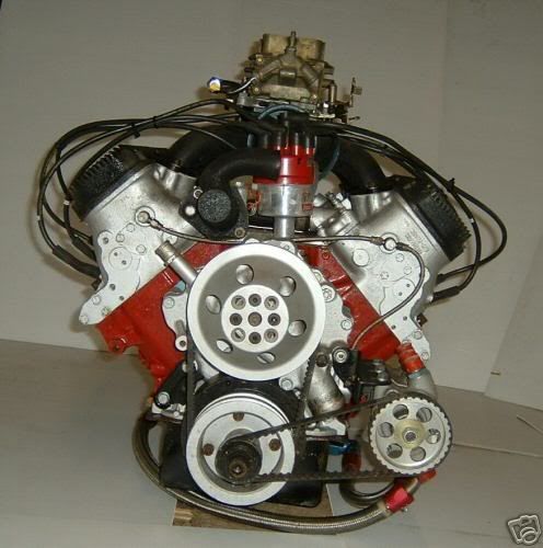
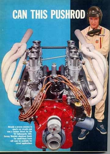
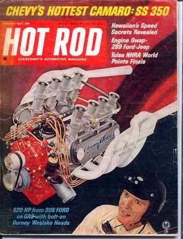
just found some interesting images of the weslake 2-valve GT40 V8 heads, plus another 2-valve race motor making 100bhp/litre........interetsing port angles......looks like 45 degrees to the cylinder axis.........I think on the Repco-brabham 3.0 V8 from around 1967 the intakes were actually pointing outwards - indicating less than 45 degrees!
|
||
|
|
|
|
19 Feb 2007, 12:23 (Ref:1845454)
|
#81 | ||
|
Racer
Join Date: Jan 2007
Posts: 158
|
Good point - could be that the energy loss in doing a 45 degree turn in the port is more than compensated for by the gas coming off the valve seat in just the right directions? That might explain why a pure, vertical downdraft head might not be optimimum & hence give less benefit than you might at first think? So, my question is, what exactly was the configuration of those early downdraft screamers?
Late edits - I'd forgotten Weslake & Renault have inclined valve heads - there, now you can see I'm making it up as I go along! BTW The Renault I mentioned was not too dissimilar to the piccies above, i.e. near vertical inlet port going into whatever V angle they were using at the time. So, whatver the effect is, I guess it applies no matter how many valves. Last edited by Dennis.Doyle; 19 Feb 2007 at 12:31. |
||
|
|
__________________
Error 0xffff - Signature Of The Day program has gone off in a huff!
|
|
19 Feb 2007, 15:42 (Ref:1845584)
|
#82 | ||
|
Veteran
Join Date: Nov 2005
Posts: 1,406
|
tadahhhhh......3 litre repco-brabham BT24 from 1967 engine piccy......you can clearly see the inlet is way off the vertical....I'm guessing about 10 degrees, which would make the valve to inlet angle about 35 degrees.....ish
its a 90 degree V8, bore is 3.5", stroke is 2.375".......power of the last versions was quoted as 325bhp at 8300rpm 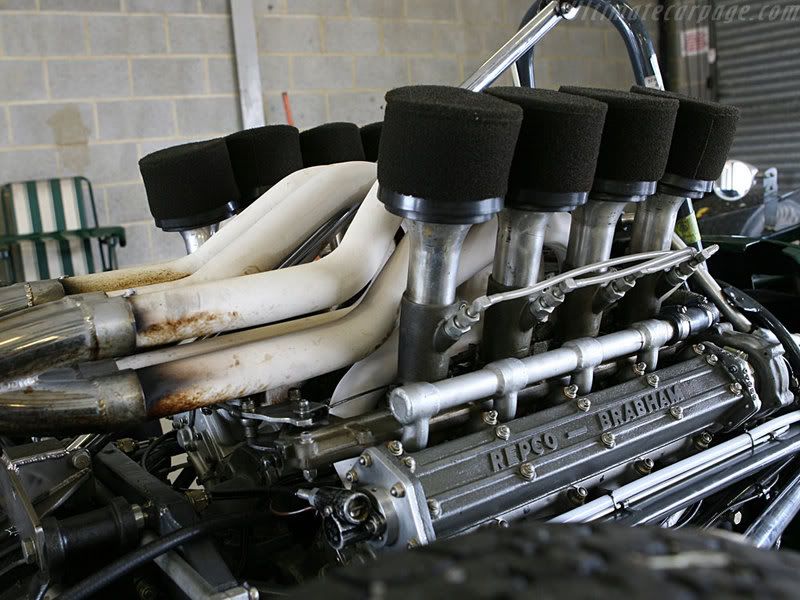
|
||
|
|
|
|
19 Feb 2007, 16:41 (Ref:1845617)
|
#83 | ||
|
Veteran

Join Date: Jul 2005
Posts: 1,981
|
Quote:
Formula 1 engines that rev to nearly 20000 rpm need ports that will not go supersonic just like us ordinary folk. The only way to achieve that is to have large ports! I suspect that the inlet valves are pretty huge too. Maximum bore this year is 98 mm so I expect the valves are as close to 49mm diameter each as they can get. On the subject of the D shaped port with a flat floor, accepting the premise that you want to reduce the area of the port to increase port speed, this is not a bad way of doing it. First, because reducing the cross sectional area concentrically would be tricky to achieve and secondly because having a flat bottom to a port, or any part of the inlet tract carrying air and fuel mixed, is a very good way of achieving evaporation of any fuel that 'drops out' of the mixture at low speeds. In other words, it is good for maintaining fuel mixture over a wide rpm range. On the basis that bike engines offer very high bhp/litre figures and are able to run at extremely high RPMs I would find it hard to agree with you that they are not technologically advanced. Of course not to F1 levels, but still pretty high tech. Last edited by phoenix; 19 Feb 2007 at 16:44. |
||
|
|
|
|
19 Feb 2007, 17:00 (Ref:1845625)
|
#84 | |
|
Veteran
Join Date: Apr 2002
Posts: 9,710
|
I have read of square bottom exhaust ports showing slight gains
|
|
|
|
|
|
19 Feb 2007, 17:00 (Ref:1845626)
|
#85 | ||
|
Veteran

Join Date: Nov 2006
Posts: 9,427
 |
I wonder why Ilmor are having so much grief with their GP bike engine,given their track record ?. Although it might not be a mechanical problem .
It would be good to see them up the front ! |
||
|
|
|
|
19 Feb 2007, 19:26 (Ref:1845710)
|
#86 | |||
|
Racer
Join Date: Jan 2007
Posts: 158
|
Quote:
Take your points about the flat floor being easier to work & getting away from concave to help evap - hadn't thought of that & that's what makes the debating worthwhile. Why not fill em up a bit more & grind em back convex I wonder? I claim bikes are not technologically advanced for the following reasons. First bhp/litre always flatters small engines - it's all to do with scaling. If you build a half scale model, area goes down by a quarter, mass & volume go down by an eigth. Apply these to BHPs litres & I think the answer pops out. Tiny model plane engines get v. high bhp/litre - not sure how advanced they are. If you look at MotoGP, they are revving nothing like they should be given their size. If you look at a TTS V8 - a 2-litre made by puting bike engine bit onto a common crank & crankcase you see 360hp. It's quite a lot compared to a 4 cylinder Duratec, Honda or whatever, but absolutely pathetic compared to a 2.5 litre F1 engine. Next according to a biker friend of mine, they only just left the carb era. Now carbs are plenty good enough for me, in fact I've never known anything else except on road cars, but I just can't help feeling that injection & full management would be a shed-load better when you get to the extremes. It's not a fair comparison of course - how can they justify spending on R&D when they are only shipping thousands of road units a year? Anyway, I'd most certainly agree that road bikes are much closer to racing bikes than road cars are to racing cars - impossible to make fair comparisons without fiddling things I think. Re, Ilmor - didn't the technical brains die a few years back? |
|||
|
|
__________________
Error 0xffff - Signature Of The Day program has gone off in a huff!
|
|
20 Feb 2007, 08:32 (Ref:1846147)
|
#87 | ||
|
Veteran
Join Date: Nov 2005
Posts: 1,406
|
guys - I have been reading your posts comparing what we are discussing to F1 engines.........I think you are a bit off track with the comparison, the F1 flow figures are nowhere near comparable to a 2.0 duratec type race engine or a 1000cc bike engine......
by my sums, an individual F1 3.0 V10 port will be flowing 2925L/min at 19,500 rpm....... a 2.0 4cyl port will be flowing 2000L/min at 8000rpm...... and a 1000cc bike engine will be flowing 1500L/min at 12,000 rpm........ just look at the flow figures, F1 port flow is significantly higher....this just cannot be compared to what we are talking about here........I have seen big ports fail on 2.0 race motor many times - they just dont work......I am basing my knowledge of port flow on the many race engines I have worked on. the key with porting is maintaining attached flow to the port walls, any abrupt changes in port shape or cross sectional area are bad news, a port to valve angle of no greater than 50 degrees, a straight and simple runner aimed at the back of the valve.......and not falling into the bigger is better trap is the key to a good set of ports. Ref Ilmor - Paul Morgan died in a classic plane crash.......he was the manufacturing brains of Ilmor.........Mario Illien was the design brains - hence they got through it. |
||
|
|
|
|
20 Feb 2007, 14:13 (Ref:1846446)
|
#88 | |
|
Veteran
Join Date: Apr 2002
Posts: 9,710
|
2 000 liter/minute = 70.629 cubic foot/minute
thats sod all by comparisson to head flow potential which might be why flow benches are only a small part of the equation maybe my small port head will work well in reality, just doesn't look good in out and out CFM from the bench. |
|
|
|
|
|
20 Feb 2007, 15:31 (Ref:1846493)
|
#89 | ||
|
Veteran
Join Date: Nov 2005
Posts: 1,406
|
your quite right - thats sod all compared to the flow bench potential - thats why flow benches are only a guide and development tool.....a race engine port does not constantly suck air like a flow bench!...people put race engines in race cars - not flow benches.......heres how I calculated it
2 litres x 8000rpm = divide 2 = 8000 L/min for all 4 cyls ......divide 4cyls = 2000L/min per cylinder.........as a rough guide - its a pretty good representation regarding total amount of induced air per cylinder. |
||
|
|
|
|
20 Feb 2007, 22:26 (Ref:1846800)
|
#90 | ||
|
Racer
Join Date: Jan 2007
Posts: 158
|
You're dead right, me bringing in F1 was a total red herring - wish I hadn't, though I was originally thinking that it made Mototuneusa more relevant rather than less.
I still can't find any explanation of why velocity ITSELF is so important. If it contributes to mass flow that's fine - it obviously gets more working fluid in. However, at times he seems to be saying high velocity is better even if total flow is less. I'm not saying he's wrong - just asking for an explanation & him endlessly repeating high velocity does not count as not an explanation. BTW I think your sums that it requires 2000 are correct, but only as an average. Since the inlet valve is likely to be open less than half the time at best (< 360 degree duration lets say), the flow required when it's actually open is more than 4000. Since most seem to think it doesn't flow much at low valve lifts, then the true peak flow is higher still? |
||
|
|
__________________
Error 0xffff - Signature Of The Day program has gone off in a huff!
|
|
21 Feb 2007, 00:39 (Ref:1846888)
|
#91 | |||
|
Veteran
Join Date: Apr 2006
Posts: 1,916
|
Quote:
Generally I think that he is on the right track, I have never done it with this sort of gusto. I have (as said further up) experimented with the raising of port floors, however, the port voulme was generally increase to at least the original. The D shape port my head guy tried did not really work, however he widend the port as well, because it didn't work on the flow bench we need tested it on the track. THe increased angle standard shape port was successful, though. Of course not a lot is relevent to my current race motor because I now run a turbo car, so effectively I pack the head with pressure when the valve is closed. I could look at the exhaust, though. |
|||
|
|
__________________
Contrary to popular opinion, I do have mechanical sympathy, I always feel sorry for the cars I drive.
|
|
21 Feb 2007, 08:25 (Ref:1847041)
|
#92 | ||
|
Veteran
Join Date: Nov 2005
Posts: 1,406
|
considering most race engines range from 90% (and upwards) volumetric efficiency, therefore the raw figures I calculated are good as they are....hence I didnt adjust them anymore.....100% volumetric efficiency is not a bad rule of thumb........I'm reliably informed by John Hilton (of Renault F1 engine design fame) that F1 engines operate at 135% volumetric efficiency - cripes
yes mototune does not offer much reasoning behind why it works.......I have seen a recent Renault F1 V10 inlet port, and they too have a slight "kneck" near the valve opening.........so F1 are using the same principle too, although - much bigger! by my rekoning, I think mototunes method works by:- 1) a shed load more of tumble - which 4-valve engines traditionally react very well to, as the combustion burn is much enhanced......... 2) all hes doing is removing the dead flow area at the bottom of the port untill it slightly nudges the flow, as traditionally all the fast flow is in the roof of the port - therefore........ 3) creating more attached flow on the entire port - for the sound waves to bounce back and forth on the port walls.....which the port harmonics love. |
||
|
|
|
|
21 Feb 2007, 10:06 (Ref:1847133)
|
#93 | |
|
Veteran
Join Date: Apr 2002
Posts: 9,710
|
Take this 2000L a minute figure . . . . . thats the volume flowed through the engine . . . . theres a few complicated calcs to make on top of this, the duration of the cam, and its ramps and opening lift so you can proportion how much valve/port area and for what time, whilst comparing this to the overall volume of flow.
therefore the head would need to flow higher on the bench to make up for how long its closed or only partially open ? no doubt theres computer programs to do all this. or in my workshop a die grinder ! |
|
|
|
|
|
21 Feb 2007, 12:53 (Ref:1847253)
|
#94 | ||
|
Veteran
Join Date: Jul 2005
Posts: 1,981
|
Quote:
As I understand it, when the inlet valve is opened and the piston goes down on the inlet stroke, a typical 'pressure difference' between the cylinder and the port side of the inlet valve(s) is around -.2 bar at it's maximum with a wide open throttle. This is called the 'static pressure differential' - and is what you or I would call 'suck'. The amount of 'suck' is proportional to the piston speed. However the efficiency of the pistons ability to suck mixture in is also affected by engine speed. At very low speed the 'suck' is relatively weak, the suck increases as the engine speed increases until at mid engine speed the amount of suck peaks, and then the amount of suck begins to fall again. This is what gives the torque curve of the engine. On long stroke engines the piston speed is high even at low revs. On short stroke engines the piston speed gets slower as the stroke shortens. Thus long stoke engines achieve peak torque at lower speeds than short stroke engines. But the cylinder isn't filled by suck alone. Once the air/mixture in the inlet port begins to flow, the air charge attains a velocity. The velocity of the air is proportional to the amount of 'suck' and the diameter of the port. Once the air is moving it gives it kinetic energy, or 'push', which will add to the 'suck' to give increased cylinder filling. This was all worked out by a guy called Bernoulli - though he was around a bit before the IC engine! It is in this area that port velocity comes into the debate! The amount of 'suck' is pretty much fixed by the piston speed. The amount of push is determined by the gas velocity and the volume of gas that has attained the velocity - i.e. the air that is in the port and in the manifold before discharging into the cylinder. It is worth noting at this point that the amount of push varies with the square of the speed, so for example if you double the gas speed by halving the cross sectional area of the port it will gain 4 times the kinetic energy as the flow (mass) will remain the same. I think this is where there are two - maybe three - possible explanations as to why smaller ports give better power. The first of these relates to the maximum speed of the gas in the port. I have seen different values given for the maximum speed that the gas should achieve in the port, but it is in the region between mach .5 and mach .65. That is between about 165 metres per second and 215 metres per second. Apparently, up until this speed there is no detriment to gas flow through a port. As kinetic energy rises with the square of the velocity it would therefore seem a good idea to take advantage of using the maximum port velocity that gives no ill-effects in order to gain the most kinetic energy. So, if a port has been designed over-size (for whatever reason - maybe to suit a production 2.3 litre engine as well as a production 2 litre engine, for example) then there would seem to be a good argument for reducing the port size to a more correct dimension. The second reason is that even when a port goes 'over speed' the resulting turbulence will not stop the flow completely, it just stop the flow rate increasing any further. This is how inlet restrictors work. So, if the interferance to flow is for maybe only 10 crank degrees of the inlet stroke that the piston is at or near peak speed, and the inlet maybe open for 300 degrees or more, then maybe the gains to be had from a higher average gas speed over the whole of the inlet opening event are greater than the losses at the peak. Remember the area under the curve! As an extention of this train of thought, the percentage of time a racing engine spends at peak rpm is not that great. The percentage of time an engine is spent accelerating is far higher (someone with a data logger could give us some real-world numbers here!) so that the benefits from achieving extra torque across the whole power band, from the moment the engine comes on cam, is of far more interest to most of us. The third reason I have been given by a head man is a little different from both of the above. Having got 206 bhp out of a 2 litre Pinto his opinion has to be considered though..... He found out on the flow bench, by playing with many different port designs, that smaller ports worked, once the manifold and inlet system were added. He stumbled across this phenomenon and then had to find an explanation for it. First thing he pointed out is that your head may flow, say, 135 cfm at 10" with the valves in, but stick the all the inlet stuff on and the flow figures will fall. If your inlet won't flow what the port will, the port will never achieve 135 cfm, so what's the point in having all that wasted flow potential in the head? He made the ports smaller, 'just to see what happened' and improved the overall flow figure - what he called the 'all on' figure. He didn't know why, it just happened. So he turned to Bernoulli - or rather a professor at a local university for an explanation of why his smaller ports increased overall flow (though he never achieved the 135 of the head alone). The explanation was this. By creating a venturi in the head (i.e. restricting the cross sectional area of part of the port) causes the gas speed to rise in the venturi AND the pressure to fall. This fall in pressure extends back up the port towards the manifold and is in addition to the negative pressure created by the piston going down the bore, and so the manifold sees a lower pressure which gives an extra 'suck'. I can't say I'm 100% convinced - I think the real explanation is more to do with the kinetic energy added by simply converting wasted flow into useful velocity. But, really, who am I to disagree. Any profs out there??? Just out of interest (I hope) I have tabulated some examples of mean piston speeds in ft per minute of various engines @ 8000 rpm: Duratec 2.3 litre 4944 Fiat/Lancia 2 litre Twink 4737 Vauxhall XE 4523 Toyota 3SGTE 4523 Duratec 2 litre 4371 Ford 1600 x flow 4083 Cosworth YB 4047 Fiat 20 valve 2 litre 3979 Ford 1300 x flow 3826 Ford 1500 pre x flow 3826 Toyota 4AGE 3756 F1 V8 (2007) 2091 Some interpretation: To achieve the same gas speed in the inlet ports of all these engines (@ 8000 rpm) would require larger ports for the engines at the top, decreasing in size as you go down the list. To put it another way, the engines at the top of the list will produce peak torque at a lower engine speed than the engines lower down the list for the SAME port size and run out of puff (due to the ports going over speed) at a lower rpm. Last edited by phoenix; 21 Feb 2007 at 12:57. |
||
|
|
|
|
21 Feb 2007, 19:45 (Ref:1847493)
|
#95 | |
|
Veteran
Join Date: Apr 2002
Posts: 9,710
|
I might comment on that when I've read and absorbed . . . . .I'll back next year

|
|
|
|
|
|
21 Feb 2007, 21:49 (Ref:1847566)
|
#96 | |||
|
Veteran
Join Date: Apr 2006
Posts: 1,916
|
Quote:
With the previously mentioned Mazda B6 (176kW 1600 cc) motor we did have some flow tests with different induction systems. The head was conventionally ported, no raised port angles with this one. To cut a long story to a medium length we tested a couple of different manifolds (lengths), but more importantly parallel (48 mm) throttle bodies as well as a set of (45 mm) tapered TB’s. The best results were achieved with the tapers, even though they were smaller. The obvious explanation was that the engine liked to see (effectively) longer trumpets than provided with the 48’s. I looked at it a different way, I had just set my own car up with a turbo restrictor for the class I race in. after much research and bugger all directly comparable information being available (In this country you can’t just go and buy a restrictor from any old supplier, and there is bugger all info on the net - +- they all have their secrets!) Anyway, I came up with a Lavel nozzle, or more correctly a de Lavel nozzle, which is what turbo prop jets use to accelerate air to as near to super-sonic speed as possible. Armed with this information I am now of the firm belief that the reason this combination worked is because it most closely replicated the effect of the Lavel nozzle, a continually decreasing cross-section to a narrow point and then opening out again quite fast. The 48’s worked by stepping down, (wide, narrows, straight, narrows, then opens) which disrupts there airflow. The continuing reduction of cross section with the tapers accelerates the air into the port, in our case we saw the best possible flow, but the torque band is also fantastic for such a powerful small capacity motor. So I guess that the momentum of the air assists at all speeds. What does that mean? Well, your reason 1 and 3 are totally compatible to each other, Phoenix. But because we were working on the head as a constant we didn’t test 2. |
|||
|
|
__________________
Contrary to popular opinion, I do have mechanical sympathy, I always feel sorry for the cars I drive.
|
|
22 Feb 2007, 09:54 (Ref:1847896)
|
#97 | ||
|
Racer
Join Date: Jan 2007
Posts: 158
|
Not much to disagree with in the above & very thankful that people are prepared to expose themselves by putting forward reasons.
Some of the things suggested, e.g. Knighty removing dead space, avoiding significant changes of direction, rapid changes in section & keeping attached flow, sound like classical head porting, seem completely sound aerodynamics & probably apply under nearly all conditions. On this basis I’m tempted to take the risk of filling in the v-shaped grooves where the injectors used to squirt with some appropriate 'bog'. Similarly, Phoenix reference to Bernoulli is very handy. If it wasn’t for Mr. B I doubt we’d have wings, venturi ground effect cars, carburettors or be opening our inlet valves at anything like 70 degrees BTDC – it’s the enormous velocity of the exhaust gases that creates the vacuum that welcomes the new charge in. Whether it contributes much to mass flow/cylinder filling in this phase is debateable, but that’s not a criticism. Rather, if we follow his suggestion that it’s kinetic energy (M*V*V) that we need to impart to the inlet flow for the following phases then we need to get it under way as soon as possible to overcome inertia & make the required acceleration feasible. In fact I think looking at it in terms of KE instead of momentum might be the really crucial bit in understanding it – you win more on the swings of V than you lose on the roundabouts of M. If we’ve got that flow going quickly, nice & early, then we are certainly making life easier in the conventional piston suck phase & we’ve reduced the power drain from pumping losses that I’d otherwise think would result from small ports. Phoenix suggestion that we keep below Mach 0.5-0.65 is handy too as it puts a cap on the idea that smaller is necessarily better! The table of piston speeds is another useful way of looking at it. We are, after all, expecting the fresh charge to follow the piston. High inlet velocities are obviously necessary to do this, it’ll probably have the effect of scavenging the end gases from the piston face, put off detonation & we’ll win there too. (BTW I think there is a typo in the table – it’s the 1300 xflow that should have a stroke of 63mm giving a mean piston speed of 3313, partly explaining why they make lovely cheap little screamers with iron cranks). Obviously rather a lot of the cylinder filling goes on in this phase – we have 180 degrees of it (some overlapping with the phase above) and the valves are pretty wide open most of this time. Seems pretty likely that the small ports will be at their most restrictive when max piston speed & full lift coincide – say about 90-100 degrees ATDC. He’s probably losing out here, but I think we are unanimous in being prepared to trade off losses in peak flow, peak revs & peak power in return for overall gains elsewhere. Notso is dead right, in saying the port restriction won’t make much odds if the rest of the inlet system already contains a restrictor. For his situation, small ports & approaching supersonic flow probably is best. For a lot of us, the inlet system also contains a restrictor we tend to forget – it’s the chokes (aux venturis) in the Webers. My guess is they will be about the same size as the port size going into the head. If that guess is wrong, I wish to be told so in no uncertain terms, because I’ve been working on that assumption for a while (38mm chokes in ‘45s which are probably too big or 36mm chokes in ‘40s going via manifold to a 36mm orifice in my 1600 or 32mm chokes in ‘40s going via manifold to a 34mm orifice in my 1350). The Bernoulli explanation doesn’t really make sense to me in this middle phase. If we could cumulatively add to the suck by putting a succession of these nozzles/diffusers up the inlet tract I think we’d have a perpetual motion machine & where is the energy coming from to drive it? I accept Knigthy’s point that Renault have some “slight necking” near the valve opening (indeed my xflow does – but probably for totally different reasons). Might be to do with where the injectors point, might be to do with cooling caused by the expansion – could speculate way beyond my experience on that one, so I’ll stop. I also have a very vague memory that a circular cross section is not the ideal one for going round bends – something to do with the flow needing to go further/travel faster on the outside of the turn but being unable to do so at top speed so you have an odd velocity gradient ? Wish I could remember. The final phase, when the piston is going back up again, maybe for as much as another 90 degrees of crank rotation is where I think the KE explanation of small ports really wins. The piston’s now telling the flow to change direction, we haven’t actually closed the valve until that piston is doing ~3000 ft/min upwards & the KE is the only possible reason for keeping those valves open under those circumstances. Apologies for length & hope I haven’t mis-attributed/mis-represented too much above. Now, must pretend to get on with the day job whilst finding out about this ‘ere de Lavel nozzle! Last edited by Dennis.Doyle; 22 Feb 2007 at 09:56. |
||
|
|
__________________
Error 0xffff - Signature Of The Day program has gone off in a huff!
|
|
22 Feb 2007, 11:28 (Ref:1847971)
|
#98 | |
|
Veteran
Join Date: Jul 2005
Posts: 1,981
|
Apologies about the 1300 x flow piston speed - I read the wrong column on my spreadsheet and Dennis is absolutely right - even at 10000 rpm the mean piston speed is only 4142 ft/min on this engine.
The Laval nozzle is used to convert low velocity, high pressure gas in to high speed, low pressure gas. Without the Laval nozzle rockets wouldn't get off the ground, for example. Interestingly, the same head guy I mentioned previously told me that he produced restrictors for turbo engines that increased power over conventional restrictors - I guess the Laval nozzle is what he was talking about! Another interesting piece of info I came across was from Dave Vizzard. He gave a two formulae which, based of head flow and cylinder capacity predicts maximum achievable horsepower and at what engine speed it will be achieved. The formulae are: Max horsepower = 0.43 x CFM @ 10" x number of cylinders. Engine speed for peak power = 2000 / displacement of 1 cylinder (in cubic inches) x CFM @ 10" Plug your own numbers in and you get some interesting results! I found that with Zefs engine flowing 135 cfm and a cylinder capacity of 367.95 cc Mr Vizzard would expect 232 bhp @ 12024 rpm - all other things being right, like compression ratio and cam timing, inlet length and exhaust design, which would all be critical. Now this suggests to me that 135 cfm is considerably more flow than Zef needs, which in turn suggests that he MAY BE losing out by having a lower gas speed in the ports in the rev range he is using. Using Mr Vizzard's formula, with all the inlet gubbins on, if Zef's head flowed 87 cfm is would make 150 bhp at 7749 rpm. Interestingly, whatever head flow you get the amount of torque at peak BHP is the same - working out at 101 ft/lb at peak rpm and around 120 ft/lb at peak torque. This represents a VE of 102% at peak torque and a VE of 87% at peak RPM. So if you have 150 bhp, Zef, I don't think there is a whole lot more you can do, other than push the power higher up the rev range. If you can get it to rev to 9000 and you can achieve 101 CFM with all the induction on you should see 174 bhp! Once again I will add the rider that I am only quoting what I have read, but I am confident that Mr Vizzard is a reasonably accurate source of information. |
|
|
|
|
|
22 Feb 2007, 11:35 (Ref:1847981)
|
#99 | |
|
Veteran
Join Date: Jul 2005
Posts: 1,981
|
To help you visualize what is going on in tapered inlets or in Laval nozzles, you migh want to click on this link and play with the inlet design yourself. The results of the changes to speed and pressure of the flow are shown below the animated example.
http://home.earthlink.net/~mmc1919/venturi.html Effectively, in a tapered inlet you get a small loss of pressure but a considerably higher gain in gas speed. |
|
|
|
|
|
22 Feb 2007, 11:46 (Ref:1847991)
|
#100 | ||
|
Veteran
Join Date: Aug 2002
Posts: 1,686
|
Why is it that every independant test I have seen has failed to show any consistent measurable improvement for taper bodies over parallel ones on the same engine?
|
||
|
|
|
 |
|
|
 Similar Threads
|
||||
| Thread | Thread Starter | Forum | Replies | Last Post |
| Kent x-flow tappet improvements anybody? | dikko | Racing Technology | 29 | 26 Jan 2007 09:08 |
| Source for high flow injectors - 500cc/min | knighty | Racing Technology | 9 | 12 Aug 2006 15:37 |
| Air Flow thru rads | ian.stewart | Racing Technology | 16 | 23 Dec 2005 22:49 |
| Best in F1 vs. the Rest: MS goes head to head in identical equipment | enemy-ace | Rallying & Rallycross | 73 | 6 Dec 2004 21:04 |
| x-flow breathing/leaking | zefarelly | Racing Technology | 11 | 8 Feb 2003 17:58 |


 Linear Mode

